This thread contains observations, questions (to Scawen and anyone else who can answer), and test results about my fiddling around with PTH files.
I've been working on my telemetry tool for a while now, and got to a point where I need OutSim's indexed distance to display meaningful data (as telemetry is typically plotted against distance along the track, and we need a consistent distance from lap to lap). This works just fine with official layouts, as they do provide this metric, however custom layouts do not. This is a problem as plotting against lap distance can result in variations of several tens of meters from lap to lap, and causes issues such as braking points, among others, to be completely out of sync on my charts.
I decided to have a go at using an already recorded lap to generate my own PTH file, and use it to compute a "corrected distance" that would try to match the indexed distance. Before generating my own files though, I used an existing one to check my calculations. See Figure 1 for an example lap around SO6R with the XRG, with the official indexed distance and my own version. It looks pretty good already, but is shifted slightly. From my observations, the PTH file for SO6R reports node 355 (of 356 total nodes) as the finish line, however when reading the file, it clearly appears that node 18 is closer. After applying a correction for this shifting issue, the two curves line up nicely, but we're not done yet!
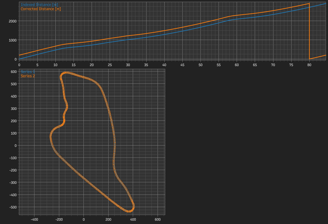
Figure 1
Figure 2 shows the difference between my corrected distance and the indexed distance. While the average error is in the order of 20mm, there are several parts where the curve trends away from zero, and sometimes diverges somewhat with a growing amplitude and alternating positive and negative values. We also have 3 very large spikes where the error goes from roughly -0.4m all the way to +0.4m.
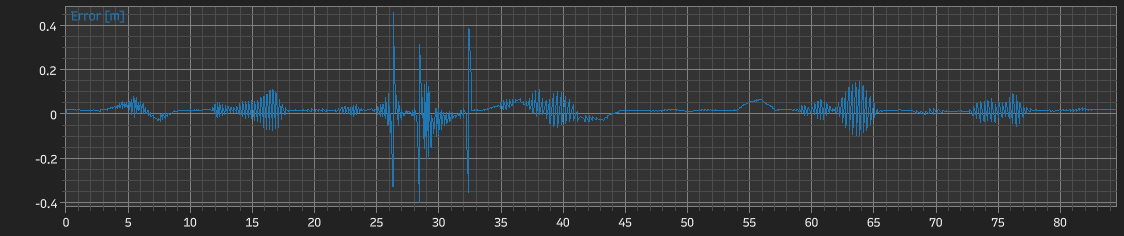
Figure 2
So far, I have an explanation for the average error, assuming the more obvious deviations are somewhat symmetrical: when fixing the node offset visible in Figure 1, I chose to set the first data point to a corrected distance of zero. Why? Because I have no way of knowing the proper value here: as I mentioned above, the finish line is closer to node 18 than it is to node 355, and even if the proper node was used, I've read somewhere on this forum that the node is not always (or even not that often) precisely located at the finish line. Note that I haven't checked this for myself, although I could, using the node's coordinates.
The other deviations are more of a problem, and that's where I would like to have Scawen's input, or anyone who can help me here. My corrected distance is computed in a somewhat naive way:
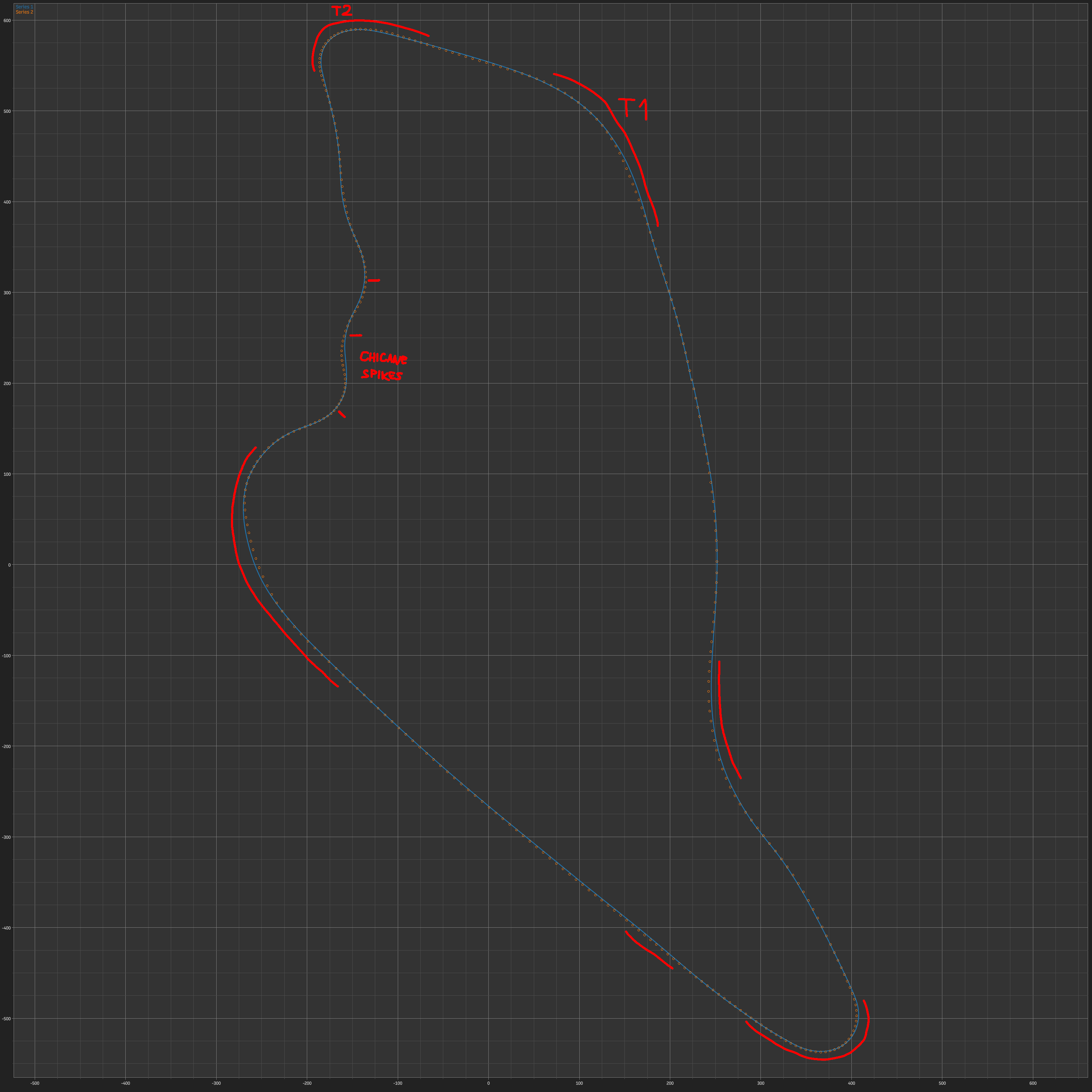
Figure 3
Now we can look at the parts where errors appear in more detail, with annotations on Figure 3 above:
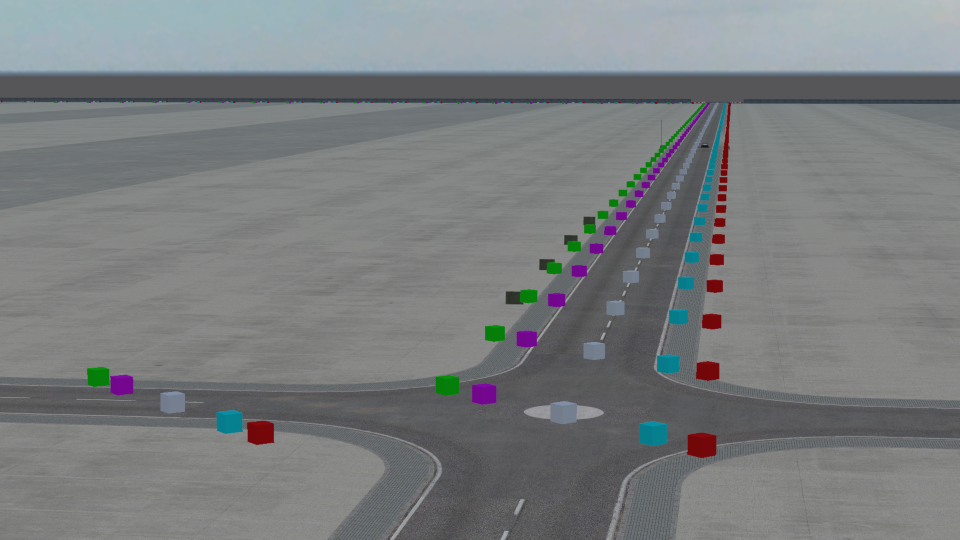
Figure 4
Alright, now I'd like to take a tangent and talk about custom PTH files. Being able to measure the length of a track or custom layout is a very good reason to want a PTH file, since (in my understanding so far) this is how LFS does it for official layouts. To mention just some of the races I took part in, GT2C this year had a custom layout for KY3 and WE2Y, and all E-Challenge races are built on LA1. We need PTH files for track measurement, and I need them for telemetry (still track measurement).
Using my Godot InSim library, I generated a simple square layout on LA1, following the roads (see Figure 4 above). I named that file LA1.pth and put it in the smx folder. I then recorded a lap and plotted the indexed distance and my corrected distance:
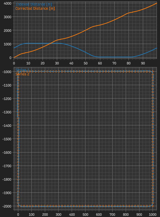
Figure 5
Here, the indexed distance goes up, then down (!), then up again. It clearly seems to follow the Y axis coordinate of the car, and it also appears that zero corresponds to the nodes' minimum Y value (-2000 to -1000 in my case, which translates to 0 to 1000). My corrected distance, however, is what I was hoping to obtain, so at least I can get usable data.
@Scawen Would there be any way to allow custom PTH files to be loaded, even just by replacing existing ones in the smx folder?
Going on another tangent here, AI: I know the subject has been tackled before, but I was also hoping to get some AI running on LA1 with the PTH file. However they do not care about it and immediately kill the engine. I also tested a custom PTH file on Blackwood, removing the .knw files while doing so, but the newly generated AI path was the original one, so they just went about the normal track and ignored my custom path.
Is AI path generation not (only) related to .pth and .knw files?
I've been working on my telemetry tool for a while now, and got to a point where I need OutSim's indexed distance to display meaningful data (as telemetry is typically plotted against distance along the track, and we need a consistent distance from lap to lap). This works just fine with official layouts, as they do provide this metric, however custom layouts do not. This is a problem as plotting against lap distance can result in variations of several tens of meters from lap to lap, and causes issues such as braking points, among others, to be completely out of sync on my charts.
I decided to have a go at using an already recorded lap to generate my own PTH file, and use it to compute a "corrected distance" that would try to match the indexed distance. Before generating my own files though, I used an existing one to check my calculations. See Figure 1 for an example lap around SO6R with the XRG, with the official indexed distance and my own version. It looks pretty good already, but is shifted slightly. From my observations, the PTH file for SO6R reports node 355 (of 356 total nodes) as the finish line, however when reading the file, it clearly appears that node 18 is closer. After applying a correction for this shifting issue, the two curves line up nicely, but we're not done yet!
Figure 1
Figure 2 shows the difference between my corrected distance and the indexed distance. While the average error is in the order of 20mm, there are several parts where the curve trends away from zero, and sometimes diverges somewhat with a growing amplitude and alternating positive and negative values. We also have 3 very large spikes where the error goes from roughly -0.4m all the way to +0.4m.
Figure 2
So far, I have an explanation for the average error, assuming the more obvious deviations are somewhat symmetrical: when fixing the node offset visible in Figure 1, I chose to set the first data point to a corrected distance of zero. Why? Because I have no way of knowing the proper value here: as I mentioned above, the finish line is closer to node 18 than it is to node 355, and even if the proper node was used, I've read somewhere on this forum that the node is not always (or even not that often) precisely located at the finish line. Note that I haven't checked this for myself, although I could, using the node's coordinates.
The other deviations are more of a problem, and that's where I would like to have Scawen's input, or anyone who can help me here. My corrected distance is computed in a somewhat naive way:
- For each point of my recorded lap, I look for the PTH node closest to the point's coordinates (right now I loop through all nodes, ideally I should use a quadtree or something).
- I then check the dot product between (next node - closest node) and (current position - closest node); if it is positive, I project the current position onto the line going through the closest node and the next node, otherwise I project it on (previous node - closest node).
- The final step is to get the path distance from the finish line up to the closest node (if dot product is positive, otherwise previous node), and add the distance from that node to the projected position.
- Bonus step: I then apply the correction mentioned above, shifting the data to fix the "reset" partway through the lap and setting the first point to zero.
Figure 3
Now we can look at the parts where errors appear in more detail, with annotations on Figure 3 above:
- 3-8s: First turn and dip, starting right after crossing the tramway tracks. There is some "noise" here, but also a clear trend moving up then down, maybe related to elevation?
- 12-18s: Turn 2, somewhat tight left hander. Noise only here, nodes are more dense in this area, and my line is slightly to the inside of the PTH line.
- 25-33s: The worst offender, chicane + uphill right hander. Extreme spikes (rough location annotated on Figure 3), not sure if 29-31s is just noise or an actual negative error.
- 34-45s: Long wide left hander and highway ramp. Noise as always, but also a clear trend, same as Turn 1, may be related to elevation or deviating from the PTH line.
- 54-57s: The dip, no noise at all here, pure trend error, likely related to elevation.
- 59-65s: Left hairpin, pure noise here.
- 73-77s: Last right turn, pure noise as well.
Figure 4
Alright, now I'd like to take a tangent and talk about custom PTH files. Being able to measure the length of a track or custom layout is a very good reason to want a PTH file, since (in my understanding so far) this is how LFS does it for official layouts. To mention just some of the races I took part in, GT2C this year had a custom layout for KY3 and WE2Y, and all E-Challenge races are built on LA1. We need PTH files for track measurement, and I need them for telemetry (still track measurement).
Using my Godot InSim library, I generated a simple square layout on LA1, following the roads (see Figure 4 above). I named that file LA1.pth and put it in the smx folder. I then recorded a lap and plotted the indexed distance and my corrected distance:
Figure 5
Here, the indexed distance goes up, then down (!), then up again. It clearly seems to follow the Y axis coordinate of the car, and it also appears that zero corresponds to the nodes' minimum Y value (-2000 to -1000 in my case, which translates to 0 to 1000). My corrected distance, however, is what I was hoping to obtain, so at least I can get usable data.
@Scawen Would there be any way to allow custom PTH files to be loaded, even just by replacing existing ones in the smx folder?
Going on another tangent here, AI: I know the subject has been tackled before, but I was also hoping to get some AI running on LA1 with the PTH file. However they do not care about it and immediately kill the engine. I also tested a custom PTH file on Blackwood, removing the .knw files while doing so, but the newly generated AI path was the original one, so they just went about the normal track and ignored my custom path.
Is AI path generation not (only) related to .pth and .knw files?